Technical Calculations
Electric Drive Calculations
The analysis verified that the servo-driven rack-and-pinion could actuate the 2 cL dosing device with an adequate margin, established the actuation cycle time, and confirmed that the electrical supply was correctly dimensioned. The method proceeded from the measured dispenser force to the corresponding motor torque, then from the transmission geometry to the motion timing, and finally to a consolidated power-rail assessment.
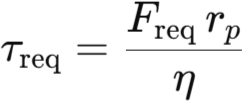
Mechanically, the dispenser presented a composite linear load arising from spring preload, seal breakaway, guide friction, and minor hydraulic effects. Substituting the project values (resultant force ≈ 12 N, pinion radius 5 mm, mesh efficiency 0.90) into the displayed relation yielded a required torque of about 0.067 N·m (≈ 0.68 kg·cm).
The selected Parallax 900-00005 servo was rated at 0.265 N·m (2.7 kg·cm), which corresponded to an available-to-required ratio of roughly 4×, comfortably exceeding a conventional 2× design factor. By inversion of the same relation, the largest permissible pinion for unity margin at the measured load was approximately 20 mm, situating the chosen 5 mm geometry well within capability.
Kinematically, the implemented motion commanded a 180° engage followed by a 180° return. With the nominal servo speed of 0.23 s per 60° at 5 V, the transit times were 0.69 s in each direction. The dosing dwell (press/dispense) lasted 2.0 s, while the refill phase was scheduled non-blocking and therefore did not extend the critical path. Using the timing expression shown above, the measured per-shot cycle time was 3.38 s.
Electrically, the 5 V rail supplied the dosing servos and control electronics. Average per-servo current in project use was modest (≈ 0.19 A), but start-up and stall transients were higher; across eight servos plus controller, driver, and HMI, the mean draw was approximately 2.1 A. The design therefore provisioned 3–4 A headroom on 5 V and placed local bulk and high-frequency decoupling near the harness to absorb transients. The 12 V rail drove the cleaning solenoid at about 3 A during activation; the circuit incorporated a flyback diode and short return routing, and concurrent 12 V loads were to be staggered if added later. Power-supply selection included at least 30 % margin per rail, and conductor sizing together with checks of MOSFET conduction losses ensured acceptable temperature rise. Grounds were maintained common and low-impedance to reduce EMI and measurement error.